August 12, 2025 Tradeshows
March 24-26, 2026 in Huntsville, Alabama Booth # TBD (TBD)
Read More
August 1, 2025 Tradeshows
Apr 19-22, 2026 in Las Vegas, Nevada Booth #C6213 (Central Hall)
July 15, 2025 Tradeshows
Aug 11-13, 2026 in Huntsville, Alabama Booth # TBD (TBD)
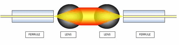
August 13, 2019 Technical Library
Summary The insertion loss in expanded beam connectors is a function of design and manufacturing process. Starting with an optimized…
January 5, 2019 Technical Library
Physical contact fiber optic connectors use precision alignment sleeves to align the mating fiber optic termini. These sleeves can be…